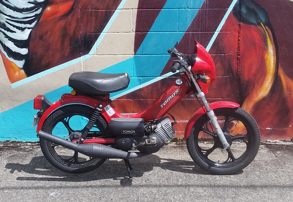
First up, I love the A55 Tomos. They are great. I’ve owned a handful, I used to work on them when we sold them at a shop, and my girl currently owns one. I’ve built 3 different gila A55, piles of other kitted ones, and run 10 of thousands of miles on stock ones. Easily the most reliable mopeds I’ve owned.
But I ain’t got rose colored glasses. Tomos have limped across the line for 40 years, updating just enough to not have to work hard. Some of the issues with the original design have never been addressed and my god is that lazy. They tend to update only when required by law. The A55 engine was their reply to increased pressure for emissions requirements. They switched back to piston port but with a much better port design, an improved head design, more heat fins for better cooling, upgraded to a multi-jet carburetor with a nicer airbox, and a catalytic converter to clean it all up. These upgrades allowed them to pass emissions and remain one of the last legal 2-strokes. It was huge step forward in design from the A35 even without reeds.
In Freedom Land you actually do not have freedom to legally go over 30mph on your moped. Tomos had built a motor capable of much more faster, but then had to hammer it slow with a pile of legally required restrictions. Their plan was pretty simple: restrict air into the carb, restrict air out of the exhaust, and restrict top speed with gearing. To fix this everyone changea the exhaust to a tuned pipe, put a 22T sprocket on the rear, foam pod filter on the carb, upjet the main and rides into the sunset.
But hold up, a pod filter has some downsides though. It gets wet and kills the motor to start with. I live in Portland and ride all the time regardless of rain, so if my bike stops running because it got wet I might as well bury it in the Willamette (that’s a river in the middle of the city to save you googling that joke). Pod filters are also really loud. Not good loud like exhaust notes either, just this annoying wheezing louder than the exhaust. It overpowers the cool 2-stroke noise and that’s unacceptable. Third the stock A55 airbox is really well designed and will actually give you a boost in the midrange. But that snorkel tube intake is a bummer.
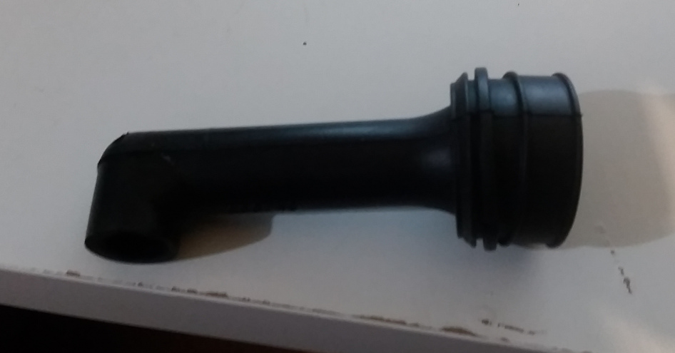
If you want to keep the airbox the options are slim. You can cut the 90 off the tube or it flush at the bottom. More aggressively you can hog the whole base open to make a larger opening while usually leaving a very rough air transition to the carb. It’s not very classy or optimal for air flow at all. So I got an idea, let’s just make a velocity stack that allows me to use the stock airbox and carb!
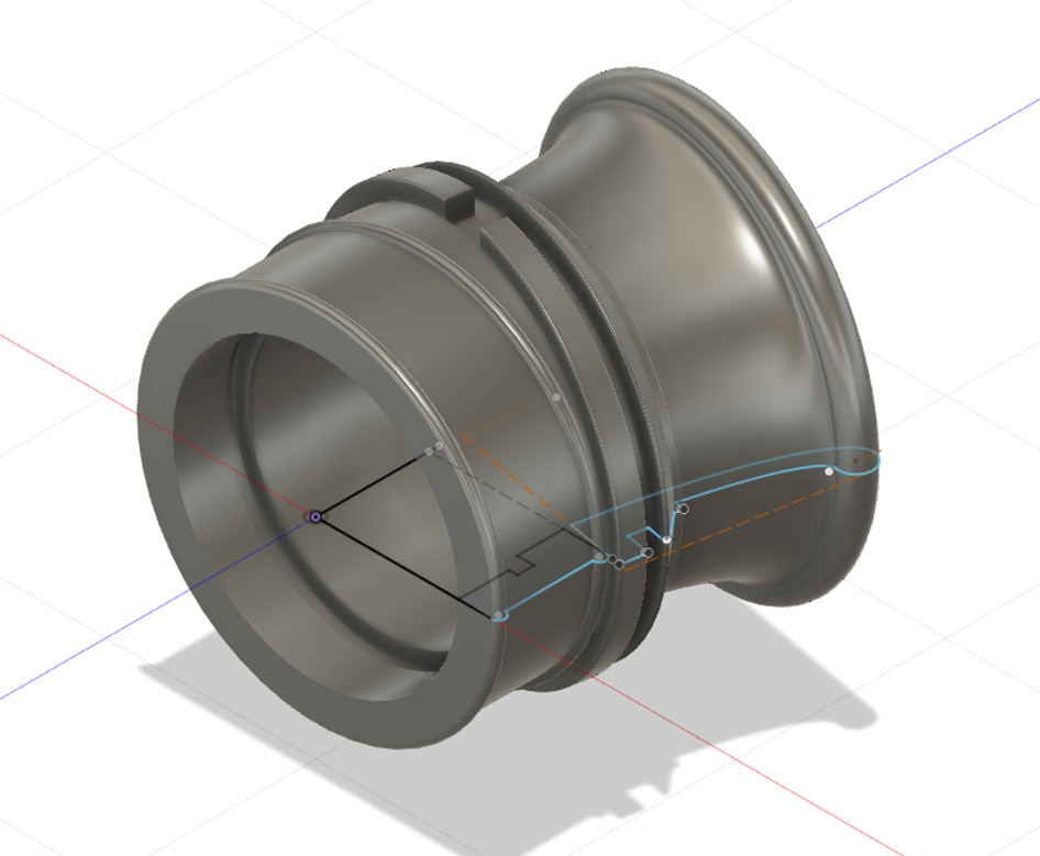
Step one was to design it. Clearly I just googled velocity stack to see what makes one good. Hmm.. looks like they need to be kind long, with a slight taper outward, and a rounded end. Welp research done, time to design the thing. At home I use Fusion 360 since it’s free and pretty user friendly. My design restrictions were simple, it has to fit in the stock airbox and I had to be able to print the mold parts. The inside of the are airbox is about 50mm wide and a couple inches in is the air filter screen so that boxed in the total size I could use. I attempted to use some resources to calculate the geometry of an optimal velocity stack but the result was a plentum too long and too large in diameter to fit the airbox so I just scrapped trying to overthink it. I didn’t want to make multiple lengths to test on a dyno and my attempt at calculating a size also didn’t work so I just chose a shape that looked nice and let the chips fall. The profile I used is an elliptical shape with a throat diameter of 44mm and a length from the carb opening of 36mm. If anyone out there can walk me through better design for such a thing I’d love to talk about it.
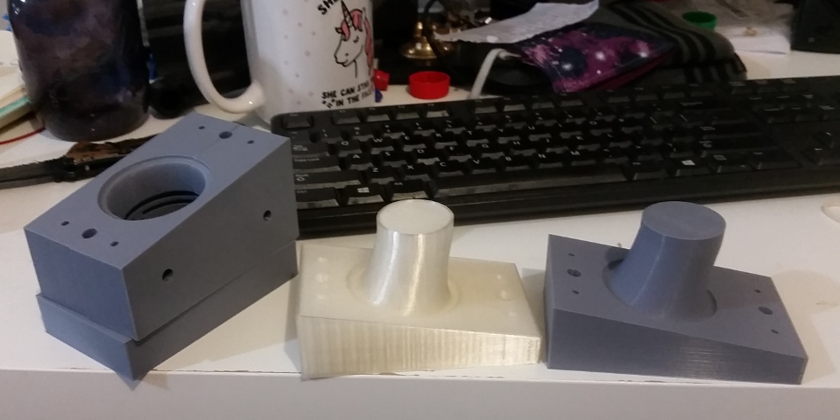
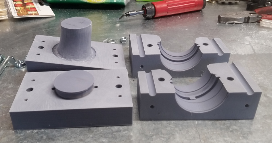
Next step was to design a mold to cast the thing. Now I’ve never done this before so back to google. Everything I’ve read uses a multi-step process of making a final positive shape part, then creating a soft mold with a rubber by pouring it around the shape in steps and putting sprues in with the part so you can pour into the mold, then filling the new negative with the final material to get a positive again in the correct material. This method would require 3d printing a positive part, then figuring out some system of holding the part to create the features I need. One of which is a hollow center. This whole process seemed really complicated and prone to failure so I held off on doing this for a long time because I just didn’t like the idea of this method. Then one day I realized I should just print a negative mold instead and cut out all that extra stuff. That was the step that moved this project from a thing I wanted to do but seemed like a huge pain in the ass to a reasonable and controllable method that made more sense to me. I won’t go into the details of how I design the mold but the overview is it’s a 4 part design. The bottom part holds the entire velocity stack interior to keep from leaving casting blend line on the air channel, one for each side, then a top with holes in it for filling and sprues for letting air back out. I put pins in the pieces to help with alignment and through holes for bolts to hold it together.
I reached out to some friend with 3d printers and received two different molds. Big shout outs to Mike Bartell and Dave Mooney for coming through on the prints, they look great. I spend some time sanding the molds for flat fitment and to help prevent leaking and to also smooth out the print lines on the inside of the horn. I stepped down from 120 grit to 320 grit in 4 steps on a flat plate and then hand finished the surface of the plenum until it felt smooth enough. Because of the intricate shape of the molds I only sanded the part that would form the inner part of the plenum and left the rest as printed.
The next issue was what do I make it out of. I had some idea of the requirements I was under: it has to be gas and oil resistant when finished, I have to be able to pour it easily at home, it has to not be very expensive, the reaction can’t be so exothermic it melts the PLA mold, it has to certain pliability, and it has to be able withstand a certain amount of strain and vibration. I landed on a 2 part urethane rubber called Vytaflex. Being my first attempt I don’t have a feel for what the different hardness ratings feel like so I just chose 40 based off of a relative hardness chart I found. I also ordered a mold release agent in a spray can they suggested I get.
Wilh all the mold parts finished and the urethan in hand, it was just a simple matter of spraying the mold with release agent, bolting it together, and filling it up. It was actually very straightforward. The mold weeped a slight bit but not enough to be concerning. Honestly I was surprised at how painless the whole process was. I let it sit overnight on my desk and popped it apart in the morning. The mold released with no effort at all. The part had a slight bit of flashing around the seams but it was marginal and easily cleaned up with a razor. The one thing I didn’t do was spray the sprue (the channel you pour the liquid through to fill it) and it took a bit of time to scrap the rubber off the plastic. Lesson learned.
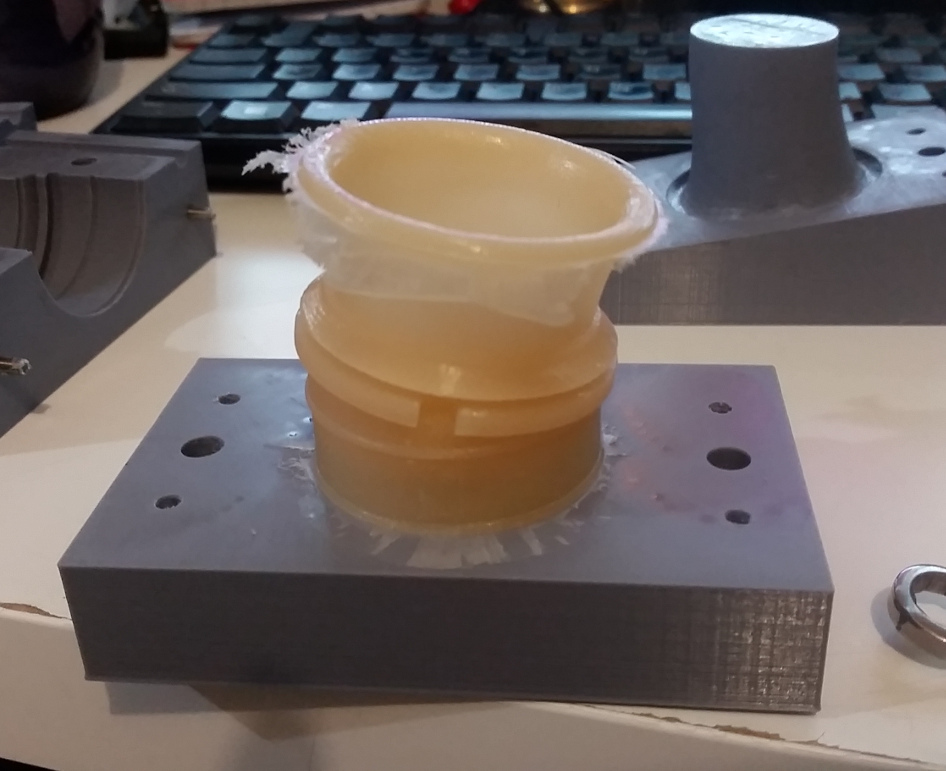
The only issue is the rubber hardness I chose was far too soft and the color was a bit bland, but dimensionally it was exactly perfect and looked great. Time to find out if it worked or not.
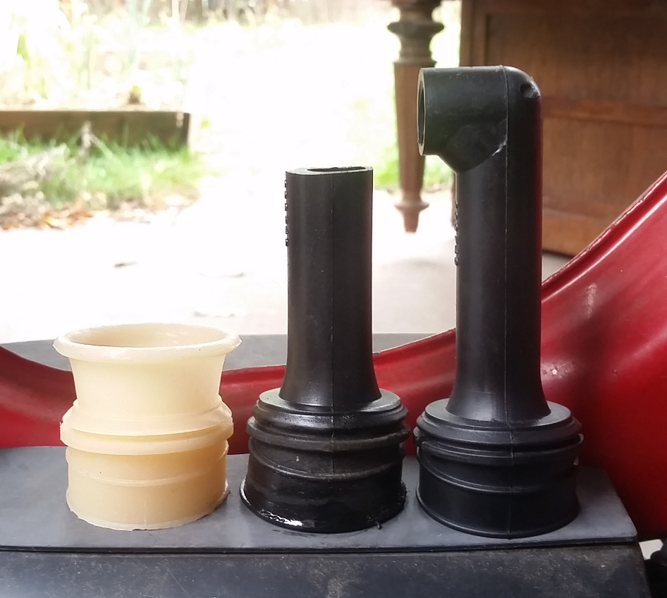
I pulled the tomos out and put a tach on it. This is a stock 2008 Tomos A55 ST with a huge amount of miles on it, a Treats black pipe, 26/22 gearing, built transmission, stock airbox with the 90 cut off the tube, and solid carb jetting. The cylinder has never been removed and the carb is the stock 14.5mm size. The ignition is a “derestricted” box from 77 but it functions exactly like the stock one as neither have a curve or a rpm limiter. It’s the same configuration I’ve been running for a while so the jetting is pretty set at 62 main, 35 idle, A12 needle. Test ride gave me a max rpm of 8100 rpm on a mostly flat stretch by my house. I swapped the carb boot to the new velocity stack, did not change anything else and recorded a max rpm of 8960 on the same stretch of road. The jetting seemed good but I could tell that I might be able to move it a point or two higher and might get a bit more out of it. For fun I threw a fully restricted intake on and measured it at a max rpm of 7540. I could tell though it was jetting restricted though, it was 4-stroke bogging at top speed and to get a better measure would have required the stock 55 main jet in the carb to see what the real max rpm was but that sounded like work so I didn’t.
Overall I feel this was a huge success. I’ve never messed with rubber casting before, or designing molds, or velocity stacks. Or really messed with 3d printers although my friends did that part. Next step is to try a harder rubber compound. This part was good for a test ride but far too soft to be used for long. Color will be added next time as well to spice things up. I need to get a pod filter to compare apples and maybe throw the whole thing on a dyno and really get an answer on all parts of the adjustments. Stay tuned right here for the exciting conclusion and to maybe eventually buy one!