For reasons of data gathering I was putting the stock 14mm carb back on the Tomos. My plan was to put the stock pipe back on and determine the jetting spread needed for fully stock bike with the Bazooka Mouth since I had never done that. I knew the jetting setup from before so I threw that in just to see if it was working fine. It was not. It no longer wanted to run over 5k rpms. I checked all the basic things but this was the exact same setup I used before and tuned in on the dyno, these should be, and were, good jetting numbers. No settings changed so I thought maybe the ignition decided to start misfiring. It’s common in CDI systems to sometimes fail in a way that causes misfires at certain rpms of engine loads and since it felt very much like that it was time to see if it was true or or I needed to look for a different problem.
So the bike is the old Tomos A55 ST workhorse. It uses the stock ignition which is a CDI with external trigger. It’s a simple and very common system that uses the exciter coil (the coil in the stator) to energize the high tension coil (the coil in the CDI box) with a capacitor (also in the CDI box) and it fires when a second smaller coil on the stator sends a signal, that’s the pickup coil. This is an almost ubiquitous system across all modern scooters and they all use generally the same specs. The primary coil sends 40-100 volts AC to the cdi box and the trigger sends a very small signal, typically 1-1.6 V AC once or twice per rotation as a trigger signal. They all have roughly the same resistance values as well. Exciter coils will generally be 0.5-5 ohms resistance across it, while the pickup will typically have around 110 ohms. This is all sorta a rule of thumb for these systems, but they should never be zero or infinite ohms (aka no continuity).
Now it’s hard to read any resistance values through a CDI box because inside of it there are diodes and transistors and whatnot, making a basic resistance test not tell you anything. Unlike a points system which is comprised of fairly basic components that you can physically see. Knowing that we can treat the CDI as a black box issue. I don’t need to know how it works, or even do any testing on it internally. All I need to know is if it gets the correct signals does it put out the expected signal (a spark). if it does get the correct signals but doesn’t spark then replace the cdi box. Easy! (it’s important to note here that the Tomos cdi is a one piece unit with the control and the coil in one piece, some are separate units and in that case you can indeed just test the resistance values across the coil but not the cdi box itself, so you can still treat it as a blackbox problem)
Ok, with that little bit of understanding lets go over how the basic steps of troubleshooting. So my bike started to misfire at certain rpms. There are a couple of things that can cause that. The wires connecting everything could be loose, corroded, or grounding somewhere unexpected, or the spark plug, the plug wire, or the plug cap could be bad. These are all easy things to test and I quickly ruled them all out. That only leaves a bad CDI box, a bad stator, or a bad pickup coil.
The next was to measure the resistance values of the two coils in the stator. The exciter coil was right in line with what I expected. Then I measured the pickup coil and received around 360 ohms value. That’s not in the expected range, but it’s also not crazy high or zero either. It’s a suspicious value.
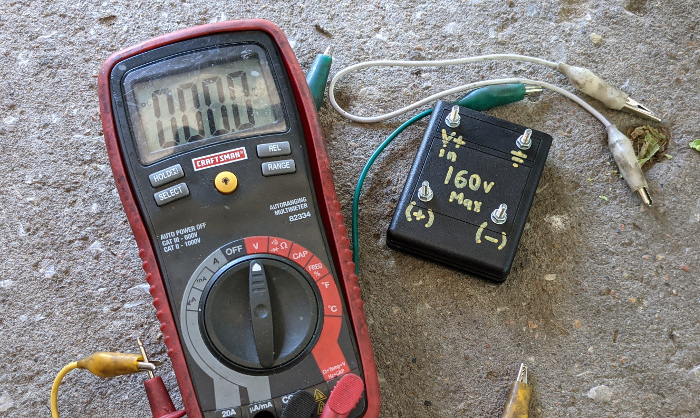
Since it wasn’t a clear failure I needed to see if the pickup coil was producing the correct voltage. You can measure this with a standard voltmeter on the AC Voltage setting. Just hook up the leads between the pickup signal wire and ground (or the white and black wire on the A55 ignition since it does not ground). You can either crank the motor over with the pedals or use a drill on the stator to rotate it at speed. If you can’t maintain a steady rpm on the crank (like when using the kickstarter) often the multimeter can read it or it won’t hold the signal long enough for you to read it. In that case I use a simple Peak Voltage Detector. It’s a simple device that will hold the highest voltage value from it’s input long enough for you to read it with a multimeter in DC mode. It gives you enough time to measure it when you otherwise would not get a signal long enough to read.
So I know that if I am measuring the voltage AC out of the pickup coil then it should be about 1.0-1.6v AC on the meter but if I am measuring it with the peak voltage device then it’s going to read much higher. The reason for that is pretty simple, reading AV voltage is not really reading the true voltage peak but just and average voltage over time. This is referred to as the Root Mean Square Voltage, or Vrms. The peak voltage detector will record the highest voltage across it, the peaks of the AC wave and then you read that value in DC mode. This will be a much higher value and can be very helpful for determining the strength of the system.
I measured the output of the pickup coil in VAC at 1.0V and again with the peak voltage detector at around 13 VDC. I used a drill to crank the motor so I could get a steady rpms. Both of those values told me it was well within range but I had another test to try. I’ve seen, on rare occasions, a pickup coil produce the correct voltage but not every cycle, basically not triggering every rotation. To check that use the frequency or hertz setting on the multimeter (if it has it) on the same wires and using a drill to get a steady rpm, and read the frequency value. The pickup should only trigger once per rotation so the hertz should be the same as the drill rpm. My drill had a max rpm of 850 rpms and with a load of the motor I estimated probably about 750 rpms. The meter read 12.99 hz, or 12.99 triggers/second*60 seconds/min to equal 780, so pretty much what I was expecting. The pickup coil seems to be doing just fine.
I then tested the exciter coil and it was also well within the normal spec, I expected 40-60 VAC output and it was right in line with that. With the stator test completed, and with all of them passing, the next step was replace the cdi box and see if it fixed the problem. But I wanted to go over how to build the PVD real quick because they are pretty handy.
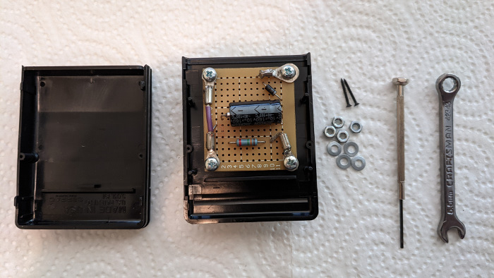
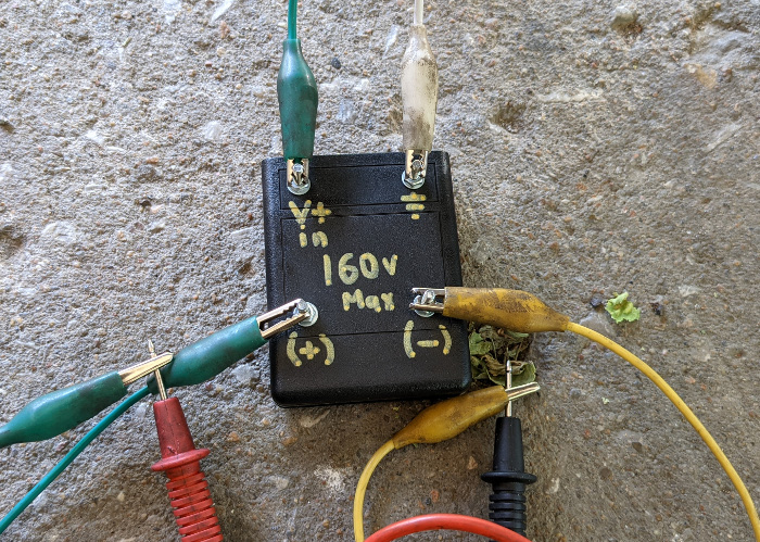
I built mine with a cheap diode, a decent 160V capacitor, a 1.3million ohm resistor, a small prototyping circuit board, some small bolts, and a plastic housing I found. I supplied the diagram below for how to electrically connect it together. Basically I just use alligator clips to connect the device to the circuit on the bike I am trying to test and then a couple more to my multimeter set to DC voltage. Then I crank the bike and see what my readings are. People with some basic electrical background would recognize this as a standard R-C circuit and it is. It’s very useful for measuring the spark strength too going to the plug, which is very difficult to record with just a voltmeter. These also work great for points systems since they tend to be much more marginal on voltage outputs as they degrade.

By itself it’s a useful tool, but I do understand that you do need some information to use it effectively. If I didn’t just know the voltage ranges I was expecting to see offhand it would be hard to find that info. It can be found usually in really good factory repair manuals but that’s not real common on these kinds of bikes and for aftermarket not really anywhere. I’ve just measured a lot of stuff over the years and know generally what I’m looking for. I feel it’s one of the reasons in the moped world tend to hate CDI units. It’s a mystery box they can’t take apart or measure directly. I get that feeling but with some simple deduction you can figure out what’s wrong. CDI’s are good, they just need the right understanding. With all those cheap cdi’s out there, it should be easier to find info to diagnose issues. Hopefully this will help someone figure their issues out.
Now for myself on this specific job, after I replaced the cdi box the bike ran exactly the same, still misfiring. Well, I know the ignition is good so I swapped the carb back to the 17.5mm one and it ran just like before. Guess I just gotta figure out why the old carb with the previously good settings no longer worked. I at least didn’t waste a lot of time replacing cdi stuff that worked fine with some proper testing. But I still don’t fully know what went wrong, just what didn’t go wrong. Sometimes it be like that.