I had an idea to have a tool that I could attach to any bike and record acceleration times between any two speeds to aid in tuning. For the express purposes of determing if the bike was getting faster or slower while I was tuning. Smart people might say they already have this technology, in the form of telemetry systems and also a basic phone gps mapping app. Those people would be right. Telemetry is super cool, but expensive to build and install. Plus you have to use other peoples software and a ton of custom fab to put into a vehicle, much less swap it around to different bikes often. GPS phone apps are awful for high level of accuracy and I’ll hear no more on the subject.
Besides I’ve been hearing so much about the world of Arduino and I was dying for a project to use it for. My plan was simple: a Trailtech vapor but with the ability to record elapsed time between two set speeds. When I am tuning a bike I want to know if it is faster or slower. I have traditionally relied on my ass to guide me but it’s not exactly 2-sigma verified. The cool guy solution is to tune on a dyno, but damn I ain’t made of money, storage space, or forgiving neighbors. So this will be the next best thing. If I can accurately and reliably measure the time it takes for a bike to say accelerate from zero to 40mph, or 20mph to 60mph, then I don’t need the actual horsepower numbers, I just need a relative value to know if the changes made it slower or faster. If it takes less time, even if by half a second, then we are getting more power. The theory was simple.
I had a couple of big problems. I knew nothing about Arduino or how it worked. I also only had a tenuous grasp on electrical theory. Although I’ve been playing with electrical stuff since I was a kid, taken a couple of electrical engineering classes, and worked on countless electrical systems over the years it still might as well be magic to me. I have also done many small programming projects and had a class in that as well. But again this would probably be a big step up in terms of conceptual understanding. Then I have to physically construct the device. So far this seems like a daunting list. But I figure if I take it in small chunks I can climb the hill.
My first step was to order a beginner kit and order a basics guide. I chose the Elegoo Super Starter Kit and this Programming Arduino sketch starter book. I then spent about a month completing the contents of both. And frankly they were very starter, as advertised I guess. I looked up other peoples efforts to make simple speedometer, mostly for bicycles. Again I found them to all be very simple but functional. These were all very helpful and I recommend them to anyone that’s interested in the subject but I knew I was going to need something more complicated.
The other basic supplies I picked up were a breadboard, a grip of jumper wires, and a good soldering station, a Hakko FX888D, which I highly recommend. There are a lot of other things I bought slowly along the way but these are the basics you need to really start, or at least I did.
So with my limited knowledge, my plan was use a reed switch for the wheel pickup and a magnet on the wheel to record the rotation. Basically just like the setup on a Trailtech. The arrangement was very simple to program and to setup on the breadboard. I also picked up a Adafruit RGB LCD shield kit for 2 pins for the onboard inputs and the screen output. It’s a very slick setup that has 5 button inputs and a backlit lcd screen and runs on only two pins from the board. I later learned it used the L2C system but at first I didn’t know what that meant other than I could still use the other pins on the board for inputs and measuring. (Side note: Adafruit so far seems to be the coolest arduino company I’ve found, but let me know if there are other one I don’t know about)
My first setup ran a simple program. It would read if the sensor triggered and the set a timer to record how long until the next trigger signal. It then calculated the speed based on the wheel diameter and the elapsed time. This was the moment it started to dawn on me how hard this was going to be. A reed switch is very noisy as a signal. Now I did not understand what signal noise was yet. Turns out when trying to read a signal from a physical switch it actually contacts a whole bunch of times very rapidly, signalling the computer every time. This is called “bounce”. You can setup debouncing systems, either in the code or in the circuitry, which will ignore all the triggers a period of time after the first one so you don’t get these errant signals. But no matter how much I tried I couldn’t get a clean signal, probably because I’m dumb. So I looked around and found a much more complicated solution, a latching hall sensor! It would still sense a magnet but will only trigger once until the field moves away. It’s more complicated to wire up and more expensive, but it gives that super crisp signal I was looking for. A smarter, more experienced person will tell me how I could have just done one simple trick to make the reed switch work but as I stated earlier, I’m dumb, so I did this.
I also needed a way to start the timer. Well, not start specifically but to prime it. The idea was to hit the button on the handlebars and set a start condition. then when it detects you have hit the defined starting speed the timer begins. I didn’t want to have to try to time hitting a button while riding when I hit a specific time this seemed like the best solution. I also didn’t want to have the button on the box itself since it would be cumbersome to try to activate it while riding. I selected a Motion Pro universal dirt bike kill switch with a short to ground style button to use. Which seemed good until I moved from the bench to the bike and it grounded to the bike frame. This played hell with the signal until I isolated it. Again this may seem obvious but see above.
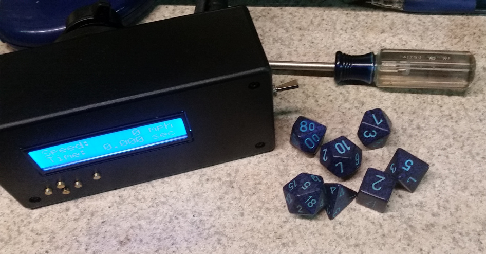
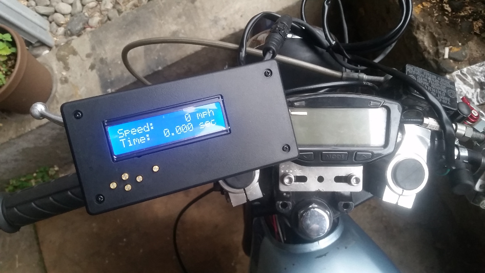
The main arduino board has the ability to attach these inputs into it directly but with the LCD shield it would be clumsy to try and attach them so I bought this Adafruit protoshield and some extended adapter so I could stack all three. I then attached the inputs directly to this board. It makes life easier because I can just remove it, add or modify it, and pop it back in. The downside is the stack of stuff is kinda tall but it’s a fine trade for ease of use. At the time I was working at a machine shop. Real old school place. It had a handful of manual machines and cnc stuff and I could use any of it at my leisure. I picked up a plastic project box from a local supply house and milled all the holes I needed to make. I also turned out some small brass buttons on a lathe and glued them to a rubber back. This acted to extend the buttons to the surface of the box and made it a little classier. I also purchased a cell phone handlebar mount and modified it to attach the box. It has a ball pivot with a threaded clasp so I can quickly remove it from a bike. It was a bit pricey but it was all metal and mounts really nicely, even if it is tall.
The activate switch was already bar ready so that was easy, but my solution for the hall sensor wheel pick was….less clever. I covered the small pcb board with hot glue. It sounds stupid but it was water proofed the electronics and didn’t impact the sensor. So whatever, I enjoy a mix of hilarious misuse of expensive equipment and low tech git-r-dun solutions.
That covers the physical construction but then came the code itself. Normal operation just needed to be a speedometer, then the system for the acceleration timer. I also wanted to record a series of runs and then be able to average selected runs. I figured this would help average out testing. Throw in a simple way to edit the parameters on the device and it seemed simple enough.
I’ve done enough coding over the years to understand the basics here but I ran into problems almost immediately. All of the example code showed how to use interrupt timers while mading it look so fun and easy. They lied. Or more accurately they explained how they work in the most basic terms only. On my setup, when the wheel makes a full revolution, a magnet passes by a sensor that sends a signal to the ecu that the event has happened. It is up to the code to figure out how to handle that signal correctly. In the hardware you have two main ways to see if a sensor is triggered. You can either set code to check to see if it is triggered every loop of the main program or you can set it to operate as an interrupt signal. If you plan to check every loop it only works with very basic code because it can miss the signal if it doesn’t check at the exact same time it is triggered. The better solution for my intent is using an interrupt. This is a special setting that will trigger special code when a signal is detected. If there is no signal then the main code loop just does whatever it was doing before. It’s so simple and easy to use! But then why did I keep having problems?
This was when I wandered into the desert. The empty expanse outside the safety of easy answers but a long way from the oasis of deep knowledge. The place where projects die. It seemed there was no bridge between the simple beginner tutorials and the secret information I needed. All I knew was I had programmed what I thought I needed based on how it had been explained to me. But it didn’t work. Not all the time at least. The worst kind of not working.
There are two major components in the only calculation I care about, when does the wheel sensor trigger and how long since the last trigger. The issues in how the interupts specifically interact with the main loop and how to read timers have a lot of depth to them in how to code for them correctly. And for some reason it’s almost never explained anywhere. It took me a long time to find the actual information I needed that contained the right mix of depth, explanation, while being simple enough to understand. So for those it would benefit here are the links I found: timers, interrupts. I originally wrote an in depth discussion of this but it was long and boring (probably? I think it’s interesting but the links explain it better than I really can anyways). If you are interested in my code I keep it updated on Github right here!
With the correct understanding of how the interrupt and timer systems worked I finally had code that would always work, it was time to move from bench to bike. And damn if that didn’t add more issues. The first issue is the ignition throws a lot of random electrical noise into the air. Enough to cause both of my remote triggers to go haywire. As soon as the bike would start it would trigger both constantly, rendering the whole thing useless. The solution was pretty simple though. A switch to a resistor plug quieted the system it would work. Whooo. Finally. So far our story has taken 6 months of my time.
Since then I’ve used it on multiple bikes to really speed up tuning. Sometimes the overall changes have been dramatic for the tune. It’s been really helpful. Mostly it sits on my old moby and tells me it does 40 slowly. In the future I plan to add a tach but that throws a whole bunch of issues I haven’t been able to sort yet. Hopefully this winter I’ll spend the time to figure it out. I also have to redo the wiring and shield the whole thing better from EMF noise because it still does not work on some bikes due to the electrical noise. There are a whole bunch of special requirements to shield connecting wires that I did not do (nor did I know I needed to do). Honestly this is an ongoing project that has at least 3 more major revisions before I’ll be really happy with it. It’s a lot to learn and I’ve probably made every beginner mistake. It’s almost like this is hard or something.